
What Is PCB DFM?
PCB DFM, or design for manufacturability, is the process of reviewing a printed circuit board design before fabrication and assembly to confirm that it can be produced reliably. A good DFM review checks whether the design matches real manufacturing capability, not just whether it passes CAD tool rules.
For hardware teams, DFM helps prevent avoidable delays such as fabrication holds, solder mask issues, drill problems, panelization changes, assembly errors, and rework. It is especially important when a project moves from prototype to production, where small layout decisions can affect yield, cost, and delivery time.
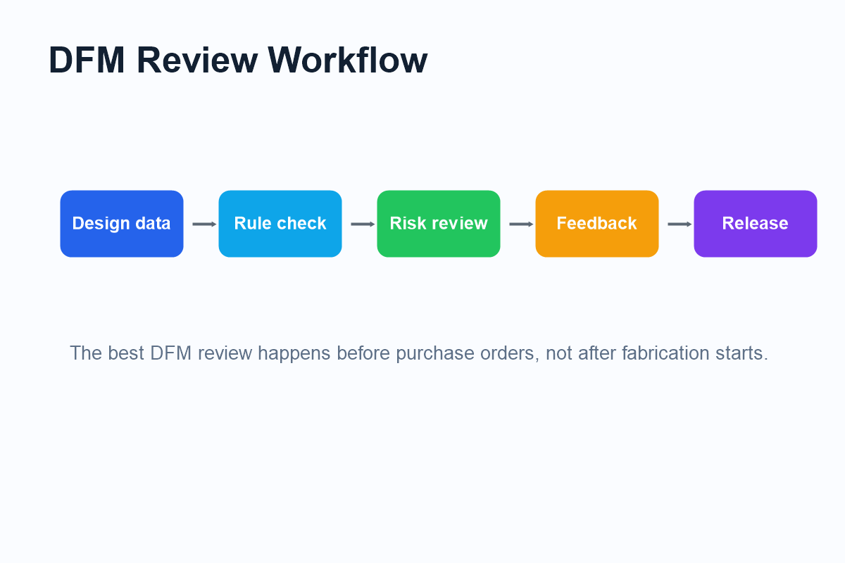
Why DFM Should Start Before Quotation
Many PCB problems become expensive because they are discovered too late. If a design is reviewed only after a purchase order is placed, the manufacturer may need to pause production, ask engineering questions, request new files, or propose rule changes. This can create delays even when the design concept is correct.
DFM is more useful when it happens before quotation or before production release. At that point, engineers can still adjust trace spacing, drill sizes, copper balance, solder mask openings, panel rails, test points, and assembly notes without disrupting a build schedule.
Fewer file revisions after production starts.
Rules align with actual fabrication capability.
Assembly and inspection needs are visible early.
Core PCB DFM Rule Categories
A complete DFM review looks at multiple areas of the design. Trace width and spacing affect etching yield and short-circuit risk. Drill size and annular ring affect plating reliability and hole registration. Stack-up decisions affect impedance, board thickness, material cost, and production availability.
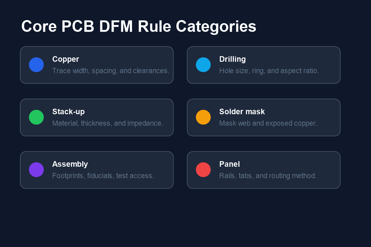
Solder mask rules are also important. If the solder mask web between pads is too narrow, the manufacturer may not be able to hold it consistently. This can increase solder bridging risk during assembly. Panelization affects how boards are fabricated, assembled, separated, and handled in volume production.
Styled DFM Checklist for PCB Layout Review
| Review area | What to check | Production impact |
|---|---|---|
| Trace / Space | Minimum width, minimum clearance, copper-to-edge distance | Etching yield, shorts, impedance stability |
| Drilling | Finished hole size, annular ring, slot shape, aspect ratio | Plating reliability and registration tolerance |
| Solder Mask | Mask expansion, mask web, exposed copper, via tenting | Solder bridging and assembly cleanliness |
| Assembly | Footprints, polarity marks, fiducials, test points | Placement accuracy, inspection, and test access |
Tolerance Questions Engineers Should Confirm
DFM is not only about checking minimum values. It is also about asking whether a tolerance can be held reliably by the selected manufacturing process. A design that pushes every rule to the minimum may be possible, but it may reduce yield or increase cost.
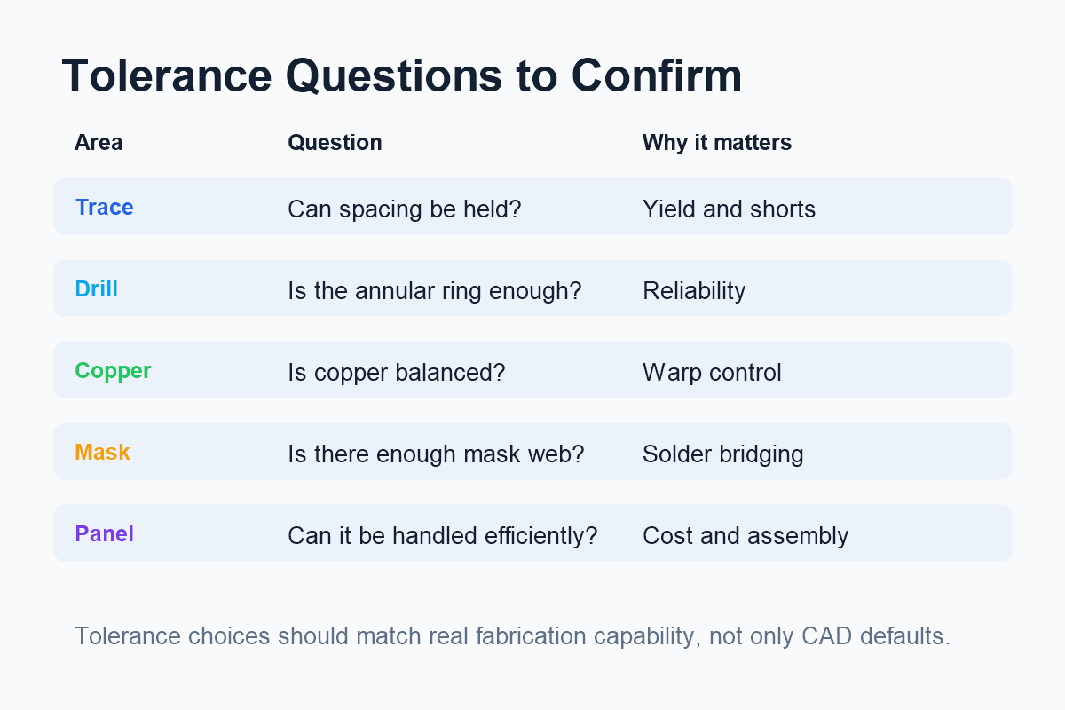
Before release, engineers should confirm whether trace spacing, hole size, annular ring, solder mask web, and board outline tolerances match the chosen fabrication class and cost target. If the product requires higher reliability, the layout should provide more margin instead of relying on absolute minimums.
Common DFM Issues Found in PCB Layouts
Common layout issues include copper spacing that is too narrow, annular rings that are too small, missing solder mask web between fine-pitch pads, unbalanced copper distribution, missing fiducials, insufficient board edge clearance, and unclear assembly notes.
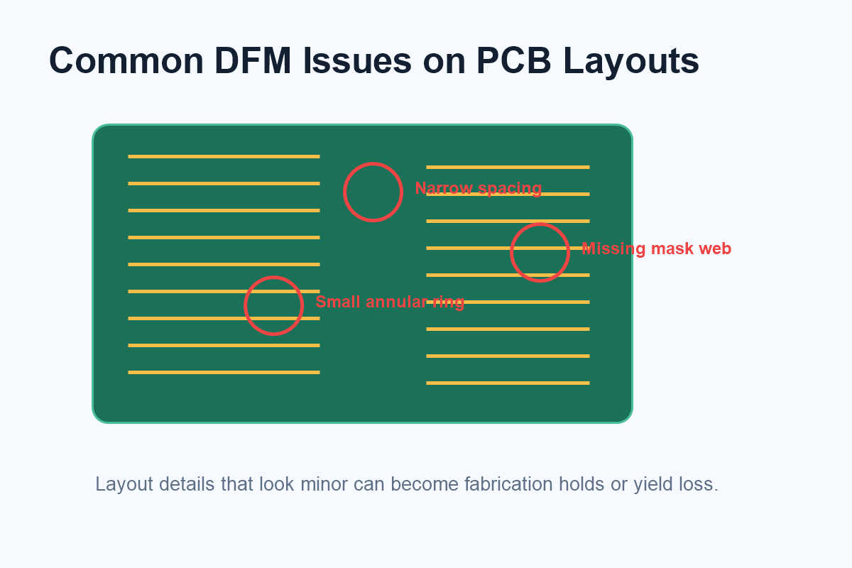
These issues may not always break electrical function in a prototype, but they can create problems in fabrication and assembly. For example, a small annular ring may pass one prototype build but become unreliable in volume production. A missing mask web may increase solder bridging risk during SMT assembly.
How CircFab Uses DFM Thinking in Manufacturing Support
CircFab focuses on PCB assembly and electronics manufacturing services, supporting projects from prototype builds to production. In that workflow, DFM is useful because it connects engineering files with practical fabrication, assembly, inspection, and quality control requirements.
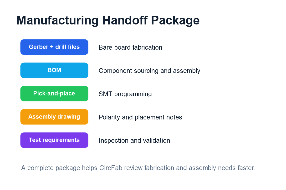
For a project moving toward production, a complete handoff package helps the manufacturing team review the design faster. Gerber files, drill data, BOM, pick-and-place file, assembly drawing, and test requirements should be consistent and clearly named.
What to Include in a Manufacturing Handoff Package
- Gerber and drill files: Required for bare board fabrication.
- BOM: Used for component sourcing, lifecycle review, and assembly planning.
- Pick-and-place file: Needed for SMT placement programming.
- Assembly drawing: Clarifies polarity, orientation, special placement notes, and hardware requirements.
- Test requirements: Defines functional testing, inspection expectations, and acceptance criteria.
DFM for Prototype vs. Production
Prototype DFM often focuses on whether the board can be fabricated quickly and assembled correctly for validation. Production DFM goes further. It considers repeatability, panel efficiency, inspection access, procurement stability, test coverage, and yield improvement.
When a design is expected to scale, engineers should avoid treating the prototype as the final production package. Design files, BOM structure, panelization, approved alternates, test points, and assembly documentation should be cleaned up before production release.
Conclusion
PCB DFM helps engineering teams reduce fabrication delays, assembly risk, and redesign. It turns manufacturing constraints into design feedback before the board reaches production. The most effective DFM review covers copper rules, drilling, stack-up, solder mask, assembly, panelization, inspection, and test access.
For teams working with a manufacturing partner such as CircFab, a complete and DFM-ready package can make the path from prototype to production more predictable. Better design data leads to faster review, fewer questions, stronger assembly planning, and more reliable PCB manufacturing outcomes.