
Why PCB Material Selection Matters
PCB material selection is one of the earliest decisions that can affect the entire product lifecycle. The laminate, copper weight, dielectric thickness, glass transition temperature, and thermal behavior all influence how a board performs during fabrication, assembly, testing, and real-world operation.
Many designs start with standard FR-4 because it is widely available and cost-effective. That is often the right choice for general electronics. However, products with high-speed signals, high power density, elevated operating temperatures, RF requirements, flexible form factors, or strict reliability targets may need a different material strategy.
[INSERT IMAGE: pcb-material-options-comparison.png]
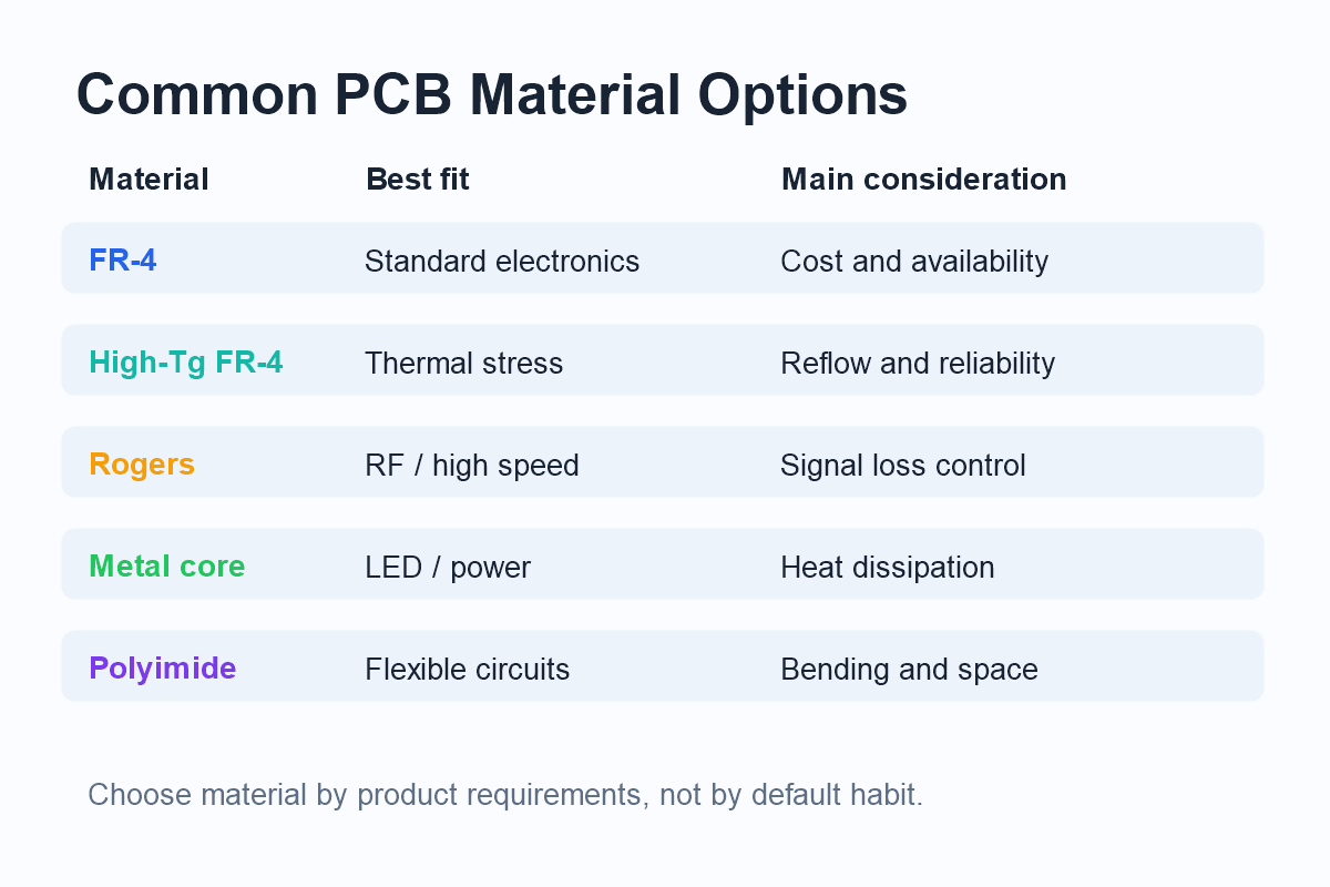
Common PCB Material Options
FR-4 is the most common PCB substrate. It works well for many consumer, industrial, and general-purpose electronics. It offers a good balance of cost, mechanical strength, and manufacturing availability.
High-Tg FR-4 is useful when the board must tolerate higher thermal stress. It is often selected for lead-free assembly, high layer-count boards, automotive electronics, and products that may see elevated operating temperatures.
Rogers and other RF materials are used when signal loss, dielectric stability, and controlled impedance are critical. These materials are common in RF modules, antennas, microwave circuits, and high-frequency communication products.
Metal core PCB materials are used when heat dissipation is a primary design concern. LED lighting, power electronics, and motor control boards may use aluminum or copper base structures to move heat away from components.
Polyimide flexible materials are used for flexible PCBs and rigid-flex designs. They support bending, folding, and compact three-dimensional assembly structures.
Material Selection Decision Path
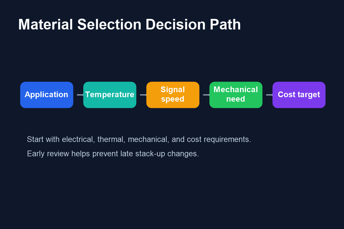
The best material choice starts with the product requirements, not with a default laminate. Engineers should consider where the product will be used, how hot it may get, how fast the signals are, whether the board must bend, and what cost target the project must meet.
Review dielectric constant, loss tangent, stack-up thickness, and controlled impedance requirements.
Check Tg, copper weight, thermal vias, metal core options, and assembly temperature exposure.
Consider board thickness, rigidity, vibration, bending, connector stress, and enclosure constraints.
Balance performance requirements with material availability, lead time, and production yield.
Thermal Performance and Material Choice
Thermal performance is one of the most common reasons to move beyond standard FR-4. During assembly, the board must survive reflow soldering temperatures. During operation, it must manage heat from components, copper planes, power traces, and the surrounding environment.
For moderate thermal stress, high-Tg FR-4 may be enough. For designs with concentrated heat, metal core PCBs or heavy copper may be more appropriate. For extreme thermal or RF requirements, specialty materials may be required. The right answer depends on component power, board size, cooling method, and reliability expectations.
How Material Affects Stack-Up Planning
Material choice directly affects stack-up planning. Dielectric thickness, copper weight, prepreg type, core material, and layer count influence impedance, crosstalk, mechanical strength, and manufacturability. If the material changes late in the project, the stack-up and impedance calculations may also need to change.
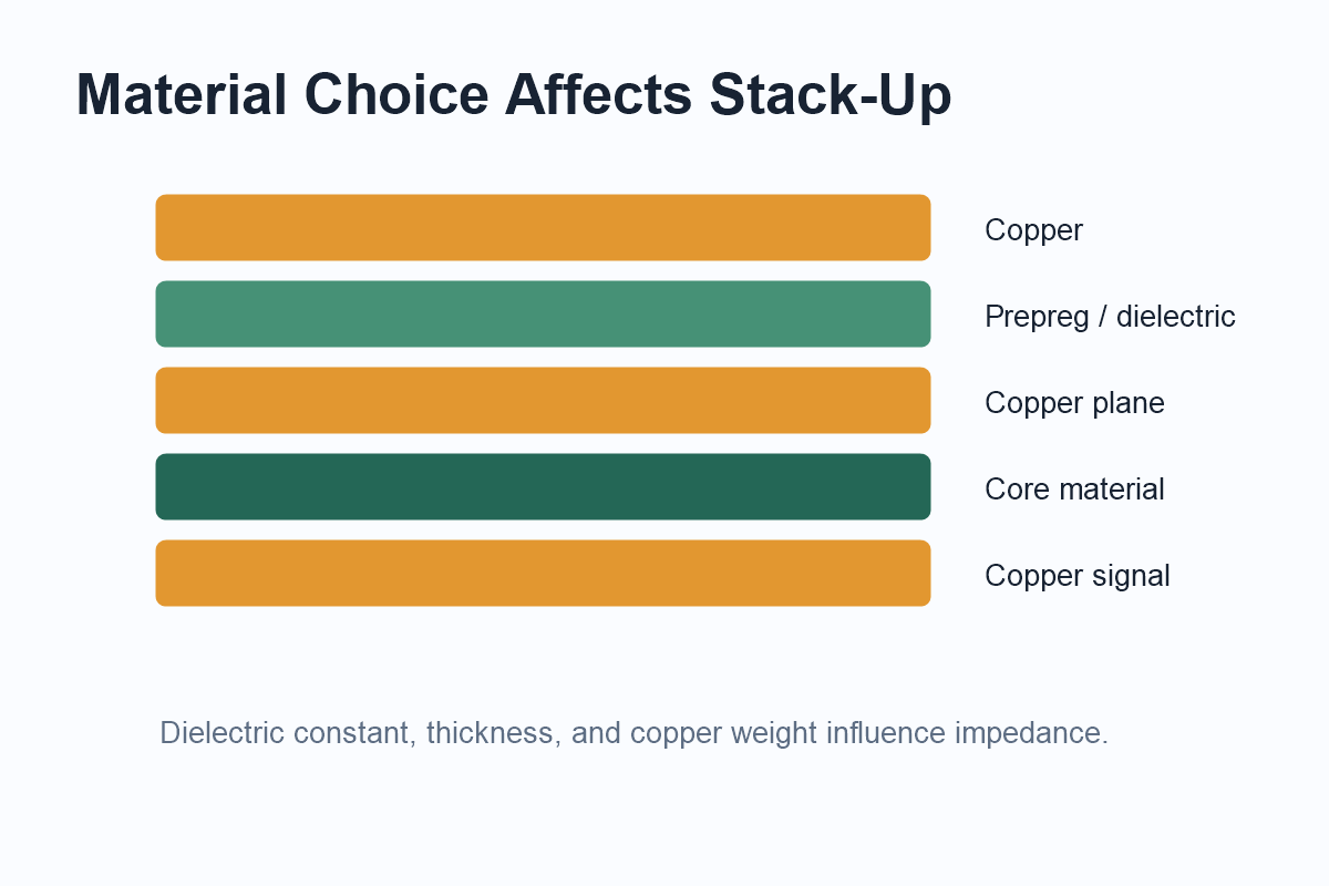
For controlled impedance designs, the PCB manufacturer should confirm material availability and stack-up before fabrication. This is especially important for high-speed interfaces, RF boards, and dense multilayer products.
Comparison Table: Choosing by Product Type
| Product requirement | Likely material direction | Key review point |
|---|---|---|
| General electronics | Standard FR-4 | Cost, thickness, copper weight |
| High temperature | High-Tg FR-4 | Tg, reflow profile, reliability |
| RF or microwave | Rogers or RF laminate | Dk, Df, impedance stability |
| LED or power | Metal core or heavy copper | Heat path and insulation layer |
| Flexible product | Polyimide flex material | Bend radius and copper fatigue |
Material Handoff Checklist
Clear material information helps avoid delays during quotation, fabrication, and assembly planning. A complete handoff should define the material type, board thickness, copper weight, surface finish, controlled impedance needs, operating temperature, and assembly constraints.
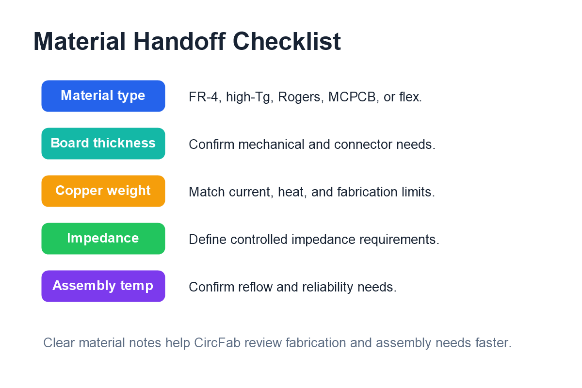
For teams working with CircFab, these details help the manufacturing review connect fabrication choices with PCB assembly, inspection, and production needs. When material notes are clear early, it is easier to align stack-up, sourcing, assembly temperature, and quality expectations.
Common Mistakes to Avoid
- Choosing standard FR-4 for a high-speed or high-temperature design without review.
- Changing material after impedance calculations are complete.
- Ignoring copper weight when current and heat are important.
- Using specialty material without confirming availability and lead time.
- Forgetting assembly temperature exposure during material selection.
Conclusion
PCB material selection is a practical engineering decision that affects performance, reliability, cost, and manufacturability. Standard FR-4 is suitable for many products, but high-Tg, RF laminates, metal core materials, and flexible substrates may be needed when thermal, electrical, or mechanical requirements become more demanding.
By reviewing material needs early and documenting them clearly, engineering teams can reduce stack-up changes, fabrication delays, and assembly risks. A manufacturing partner such as CircFab can help connect material decisions with PCB fabrication, assembly, inspection, and production planning.