
What Is a Rigid-Flex PCB?
A rigid-flex PCB is a printed circuit board that combines rigid board sections with flexible circuit sections in a single integrated structure. The rigid areas provide mechanical support for components, connectors, and mounting points, while the flexible areas allow the circuit to bend, fold, or fit into compact spaces.
This type of PCB is widely used in products that need high reliability, compact packaging, and reduced wiring. Common applications include medical devices, aerospace electronics, wearable products, cameras, automotive modules, industrial sensors, and advanced consumer electronics.
How Rigid-Flex PCBs Work
In a rigid-flex design, the flexible layers are usually made with polyimide materials, while the rigid sections may use FR-4 or other laminated substrates. Copper traces run across both rigid and flexible areas, creating a continuous electrical connection without separate cables or board-to-board connectors.
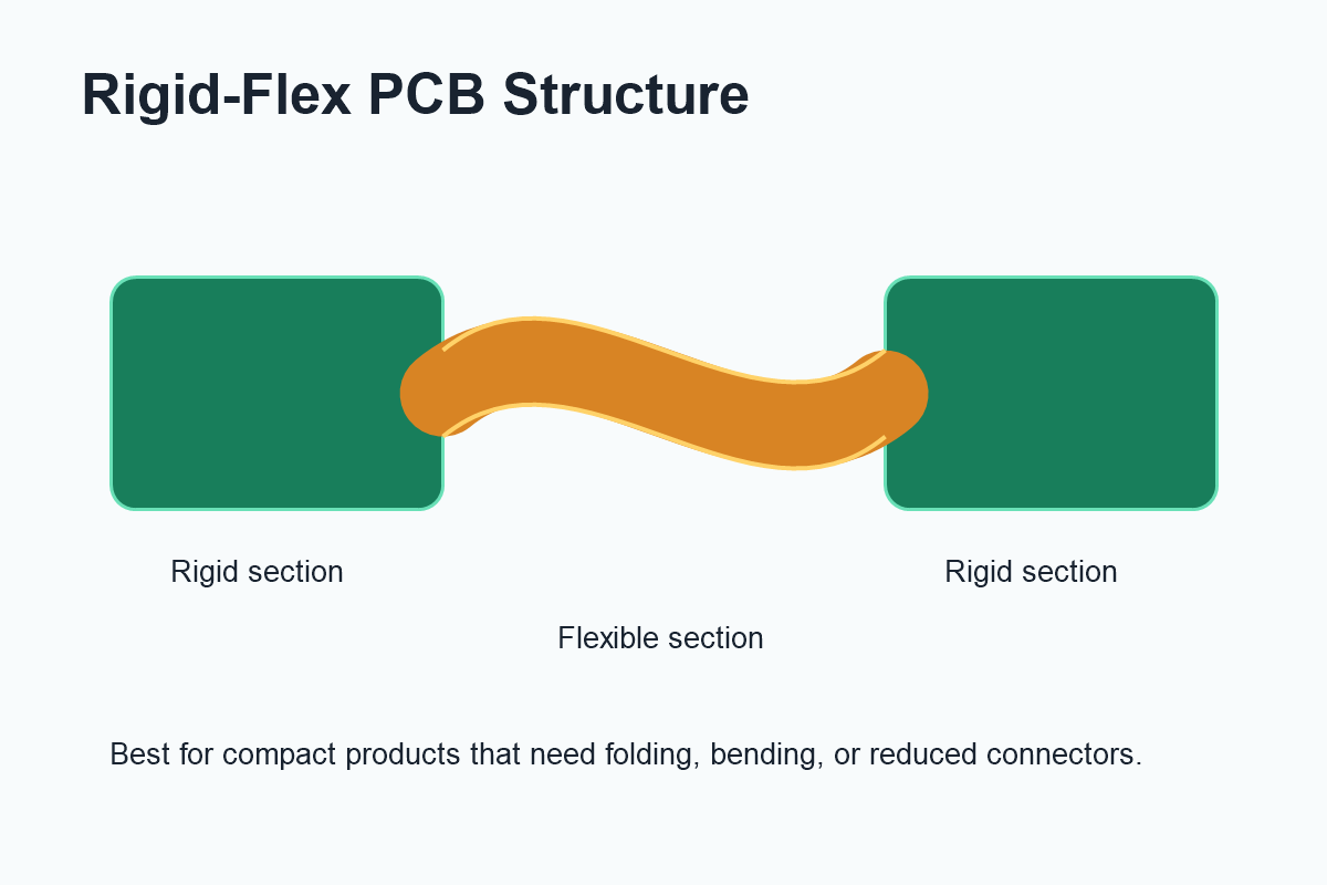
Because the circuit is integrated into one board, rigid-flex PCBs can reduce assembly complexity. They can also improve signal reliability by removing connector interfaces that may fail under vibration, repeated movement, or long-term use.
Key Advantages of Rigid-Flex PCB Technology
One major advantage of rigid-flex PCBs is space saving. Flexible sections allow the board to fold into three-dimensional product shapes, making them useful for compact enclosures and lightweight devices.
Another benefit is improved reliability. Traditional designs may use multiple rigid boards connected by cables or connectors. Each connector adds cost, assembly time, and a possible failure point. Rigid-flex construction can reduce these interfaces and create a more robust product architecture.
Rigid-flex PCBs can also simplify assembly. Fewer separate parts mean fewer manual connection steps, lower risk of wiring errors, and better repeatability in production.
Design Considerations for Rigid-Flex PCBs
Rigid-flex PCB design requires careful planning from the beginning. The bend area should not be treated like a standard rigid board. Engineers need to consider bend radius, copper orientation, layer count, material thickness, stiffener placement, and transition areas between rigid and flexible sections.
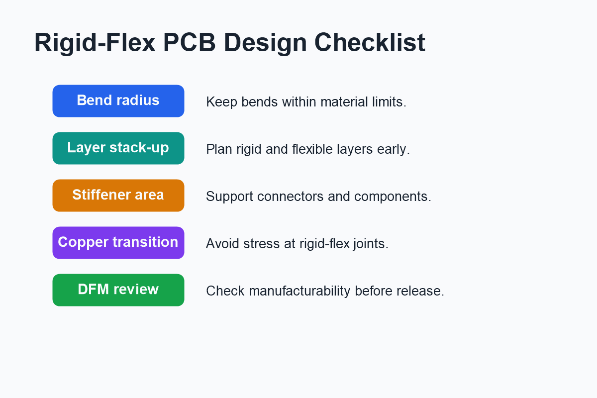
The bend radius is especially important. If the flexible section bends too tightly, copper traces may crack or the material may delaminate. Dynamic flex applications, where the circuit bends repeatedly during product use, usually require more conservative design rules than a one-time installation bend.
Copper routing should also be designed carefully in the flexible area. Sharp corners, abrupt width changes, and vias in bend zones should generally be avoided. Smooth trace routing helps reduce mechanical stress and improves long-term durability.
Manufacturing Challenges
Rigid-flex PCBs are more complex to manufacture than standard rigid boards. They involve different materials, special lamination steps, precise layer alignment, and careful control of flexible and rigid regions. For this reason, early communication with the PCB manufacturer is important.
Design for manufacturability review can help identify risks before production. Important checks include minimum trace and space, drill sizes, coverlay openings, stiffener design, adhesive flow, copper balance, panelization, and inspection requirements.
When Should You Use a Rigid-Flex PCB?
A rigid-flex PCB is a good choice when the product needs compact packaging, high reliability, folding geometry, reduced connectors, or better vibration resistance. It is especially useful when standard rigid boards and cables create too much assembly complexity or take up too much space.
However, rigid-flex technology is not always the lowest-cost option for simple products. It should be selected when its design and reliability benefits justify the added manufacturing complexity.
Conclusion
Rigid-flex PCBs offer a powerful way to combine mechanical flexibility with electronic reliability. By integrating rigid and flexible sections into one board, engineers can reduce connectors, save space, simplify assembly, and improve product durability.
Successful rigid-flex PCB projects depend on early stack-up planning, careful bend design, proper material selection, and close collaboration with an experienced PCB manufacturing partner.